Application Design and Architecture¶ ↑
- Author
-
Ariel Ortiz
- Date
-
April 6, 2017
I explain here how to write the documentation for your final project. As an example, I provide a simple Greeter web application, which is just a glorified version of the classical Hello World program but running on the web and producing results in different natural languages.
The directory structure for the application and its documentation is as follows:
greeter/
      ├─ doc/                        Folder produced by RDoc.
      ├─ images/                     Folder for the documentation's image files.
      └─ src/                        Folder for the application's source code.
           ├─ public/                Folder for the server's public documents.
           │       └─ stylesheets/   Folder for the application's CSS files.
           ├─ models/                Folder for the application's models.
           └─ views/                 Folder for the application's views (ERB files).
The builddoc.sh shell script contains the required
instructions to produce the RDoc documentation. Run the script from the
greeter directory, typing at the terminal:
./builddoc.sh
The root of the documentation should now be available at:
greeter/doc/index.html
Use any web browser to see the result.
Installing and Running the Application¶ ↑
Use this section to explain any details on how to install and run you application.
You need to have Ruby 2.x and the Sinatra gem installed in your system
to run the Greeter web application. To run the server type the
following command at the terminal from the greeter/src
directory:
ruby -I . -w server.rb
Afterwards, point your web browser at the following URL:
http://localhost:8080/
4+1 Architectural View Model¶ ↑
You must use Philippe Kruchten's “4+1 View Model” to document your application's architecture. I suggest using the draw.io site to produce the required UML diagrams.
Logical View¶ ↑
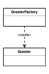
The logical view contains information about the various parts of the system. In UML the logical view is typically modeled using class diagrams.
For example, the following figure represents the UML class diagram for the
Greeter model and its factory class:

You can include as many of these diagrams as you consider necessary. Note that you only need to specify the names of the classes and their relationships. Don't include attributes or method names in these diagrams.
To include an image in this document, copy it to the images
directory and refer it as: link:../images/some_image.png. You
can use any web supported image format (PNG, JPEG, GIF, etc.).
Process View¶ ↑
The process view focuses on the runtime behavior of the system. In UML, activity diagrams are used to model this view.

Development View¶ ↑
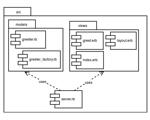
The development view focuses on software modules and subsystems. In UML, package diagrams are used to model the development view.

Physical View¶ ↑
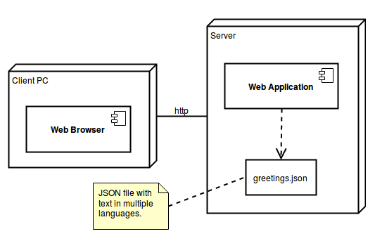
The physical view describes the physical deployment of the system, revealing which pieces of software run on what pieces of hardware. In UML, deployment diagrams are used to model the physical view.

Scenarios¶ ↑
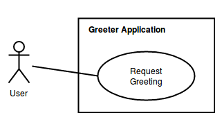
This view describes the functionality of the system from the perspective from outside world. It contains diagrams describing what the system is supposed to do from a black box perspective. UML use case diagrams are used for this view.

Patterns Used¶ ↑
Briefly mention all the patterns that your application uses and identify where exactly. In our example, the following pattern are clearly used:
-
Domain-Specific Language: The
server.rbfile consists of a series of Sinatra routes. Sinatra is a DSL for creating web applications in Ruby. -
Model-View-Controller: The application follows the classical web implementation of the MVC architectural pattern. The models (
.rbfiles) and views (.erbfiles) are stored in the correspondingmodelsandviewsdirectory. The controller is contained inserver.rbfile. -
Simple Factory: The
GreeterFactoryis used to createGreeterinstances by specifying the desired language during its creation.
Acknowledgments¶ ↑
This section is optional. If somebody helped you with your project make sure to include her or his name here.
References¶ ↑
Mention here any consulted books or web resources. Examples:
-
M. Fowler. UML Distilled: A Brief Guide to the Standard Object Modeling Language, 3rd Edition. Addison-Wesley, 2003. Available through Safari Books Online.
-
E. Gamma, R. Helm, R. Johnson, J. M. Vlissides. Design Patterns: Elements of Reusable Object-Oriented Software. Addison-Wesley, 1994. Available through Safari Books Online.
-
A. Harris, K. Haase. Sinatra: Up and Running. O'Reilly, 2011. Safari Books Online.
-
Ph. Kruchten. The 4+1 View Model of Architecture. IEEE Software, vol. 12 (6), pp. 45-50, 1995. http://www.ics.uci.edu/~andre/ics223w2006/kruchten3.pdf Accessed April 6, 2017.
-
R. Olsen. Design Patterns in Ruby. Addison-Wesley, 2007. Available through Safari Books Online.
-
Ruby-Doc.org. RDoc Markup Reference. http://ruby-doc.org/stdlib-2.4.1/libdoc/rdoc/rdoc/RDoc/Markup.html Accessed April 6, 2017.